My blog traffic shows that a lot of the visitors are looking for information on IMUs (Inertial Measurement Units) like the MPU-6050. Understanding how to use IMUs and access the data they provide can be daunting. However, I just came across a new Arduino library for getting IMU data that looks like it will make things simpler. Written by a company named Richards-Tech, the library is called RTIMULib, and can be found at https://github.com/richards-tech/RTIMULib-Arduino.
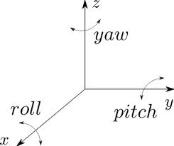
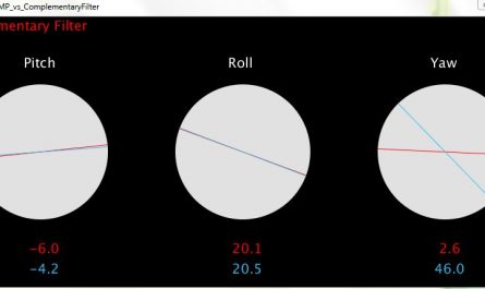
What’s incredibly awesome, and more or less unique about this library is that it comes with well-documented sample programs. I plugged in my MPU-6050, compiled and loaded the program called “ArduinoIMU”, and got what appears to be accurate data right away. The routine provides not only pitch and roll angles, but yaw angles as well, which a complementary filter alone (see the post Gyroscopes and Acceleromters on a Chip for complementary filter information) cannot calculate. Below is a sample from my IMU output. RTIMULib treats the MPU-6050 like a MPU-9150 without a magnetometer. Looking at the output data over time, I see the yaw values drifting somewhat, even when the IMU is stationary. It will be interesting to see how the yaw drift from RTIMULib compares to that from i2cDevLib directly (see MPU-6050: DMP Data from i2cdevlib for information on obtaining data directly from i2cdevlib)
[codebox 1]
I haven’t yet tested this feature, but RTIMULib also gives you the freedom to set the relative weight of the accelerometer and gyroscope in performing data fusion to obtain the orientation angles. All you have to do is change a single parameter that they call the “Slerp” factor. Other parameters are easily configurable, including the freedom to select which sensors (e.g. accelerometer, gyroscope, magnetometer) have their data included in the fusion algorithm to compute the orientation angle. Examples of how to do this are shown in the sample programs they provide.
I found a blog post where Richards-Tech discusses the algorithm used for sensor fusion. Apparently it’s a simplified version of a Kalman filter. They discuss the “Slerp” factor here if you’re looking for more information.
RTIMULib is set up to work with a number of different IMUs. If your IMU contains a magnetometer, RTIMULib has a straightforward-looking calibration routine, and instructions on how to use it. I’ve just ordered a MPU-9150 for my TinyDuino, and will be trying out the calibration routine once it arrives. I wonder if the addition of a magnetometer will eliminate the yaw drift I observed with the MPU-6050.
I haven’t had a chance to explore this library in depth yet, but its relative ease of use already makes it a very appealing option for obtaining IMU data with an Arduino. I’d love to hear feedback from anyone else who has tried it.


I have been working on related projects and am glad that you have pointed this out
I now have this running – WAY more stable – huge diff
I’m still curious of your test. 🙂
Sorry, I haven’t gotten to it yet. My 9-DOF-IMU is sitting in a drawer waiting to be put to use, but as usual, I find myself distracted by other projects. I promise to post if (when!) I get around to it.
Many thanks for your blog , it is a great help for me !
I am very interested in your tests , and I look forward to your next posts about this subject.
Recently , I understand the gimbal lock problem (while reading some replies to one of your post) . But practically, I have no solution to gimbal lock problem on my arduino code. Yaw drift and instability are problems but it seems to me that the gimbal lock problem is the main problem when using mpu6050 for real use because it can lead to a completely false result . According to many wensites , use of quaternion seems to be the solution but I still see the problem when it is converted to yaw, pitch and roll. Unfortunatly, math is not my prefered hobby so perhaps I am not able to go further ?
Anyway, congratulations for your blog !
Hello, I use the LSM9DS0 9DOF Breakout Board, but I don’t know how to use the library to run the “ArduinoIMU”. I found that LSM9DS0 library is also included. Would you please tell me where can I set the type of the module? Thank you very much!
Hallo, I conntected a Seeed studio grove imu 10dof to an arduino board. It works very well. But as a novice in arduino programming i can not figure out, how to access the fusioned vector data in ArduinoIMU.ino espacially vec.z() * RTMATH_RAD_TO_DEGREE from RTIMULib. Any help greatly appreciated. Thank you very much!
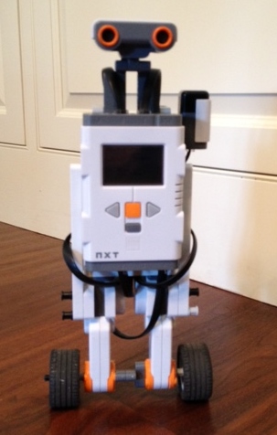
Hello there, I am making Self balancing robot, Using IMU 6050 when it runs sometime data appear random on serial monitor and robot starts to shake. Can you tell how to solve this problem. I am using DMP.
Hi,
thanks for the hint. I spent the whole day playing around with it and it’s impressive: the fusion algorithm seems to be very powerful. With proper acc calibration i don’t even get noticeable short term yaw drift. By the way: the little calibration program is also worth a note, very simple and well documented.
Also there is code for Rasperry Pi, Linux and Arduino (and more) included which is exactly what i needed.
I will also order some MPU-9250 devices next to have a best possible IMUs. I am trying to control a robotic arm with an IMU on each limb. Might become quite a challenge since the MPU-6050 allows only for 2 different I2C adresses which i hope to be able to abuse for multiplexing.
Anyway thanks for sharing your work, I am checking by once and a while have found many interesting hints here!
Hi, have you tried out your 9dof mpu9150. I have the same ic, just wondering, how to make sense of the data and process it. Post your review once you get your hands on the sensor. it would be of great help.
Hi – I’m afraid I have not used the mpu9150, and am not using IMUs for any of my current projects, so I doubt I will be looking at it any time soon. Sorry I can’t be of more help, and good luck with your project.
Hi, I am a student and I try to read the angles from 4 mpu9250. I use arduino mega2560. Do you know how I can modify the RTIMULibrary???
Thanks for the help.
Hi,
I had the same issue and could solve it successfully. What I did is to define one active and one inactive adress (since the sensor board only allows for 2 I2C adresses). So I connected all 4 sensors on the I2C bus and I connected 1 extra pin to the adress pin of each sensor. So if I want to communicate with one sensor I set it’s adress pin to HIGH and the adress pins of the other sensors to LOW, adressing all sensors with the adress which is defined by setting the adress pin HIGH. Works fine with polling at 400 Hz (I switch the adress on every cycle, so effectively I am reading all 4 sensors at 100 Hz).
No need to modify the RTIMUlib, just define your own little function.